In this article, we’ll give you a quick overview of the main CNC milling operations that Autodesk Fusion360 offers, with the goal of helping you identify the best ones for your next project.
First, we'll compare the different operations for different uses and then we will go further into each operation to offer insights on how to configure them properly.
By placing your mouse on any parameters in fusion, it opens a little help widget with a brief explanation of that operation.

Choosing the right operations for a specific task can be overwhelming given the number of options available. Let’s start with a quick comparison of the basics.
Part 1: Presentation of the Most Common Operations
Please note that there are many valid ways of milling, and that Fusion 360 offers other milling operations than the ones we’ll present in this article. We decided to focus on the ones our Mekanika community uses the most on their own CNC milling machines.
2D Contour Usage
Contour is used to make 2D cuts to free a piece from its stock or to make slots inside the piece. It can also be used to clean the inner edges after an Adaptive Clearing or Pocket operation. Think of it as a release cut you would do with a jig saw.

Pockets and Adaptive Clearing Usage
When it comes to milling pockets (basically large holes), you have 2 options: the Pocket operation or the Adaptive Clearing operation.
The main difference between both operations is that Pocket will keep a constant engagement of your mill in the stock, while Adaptive Clearing will take bites, alternating cutting and cooling, and avoid abrupt direction changes.
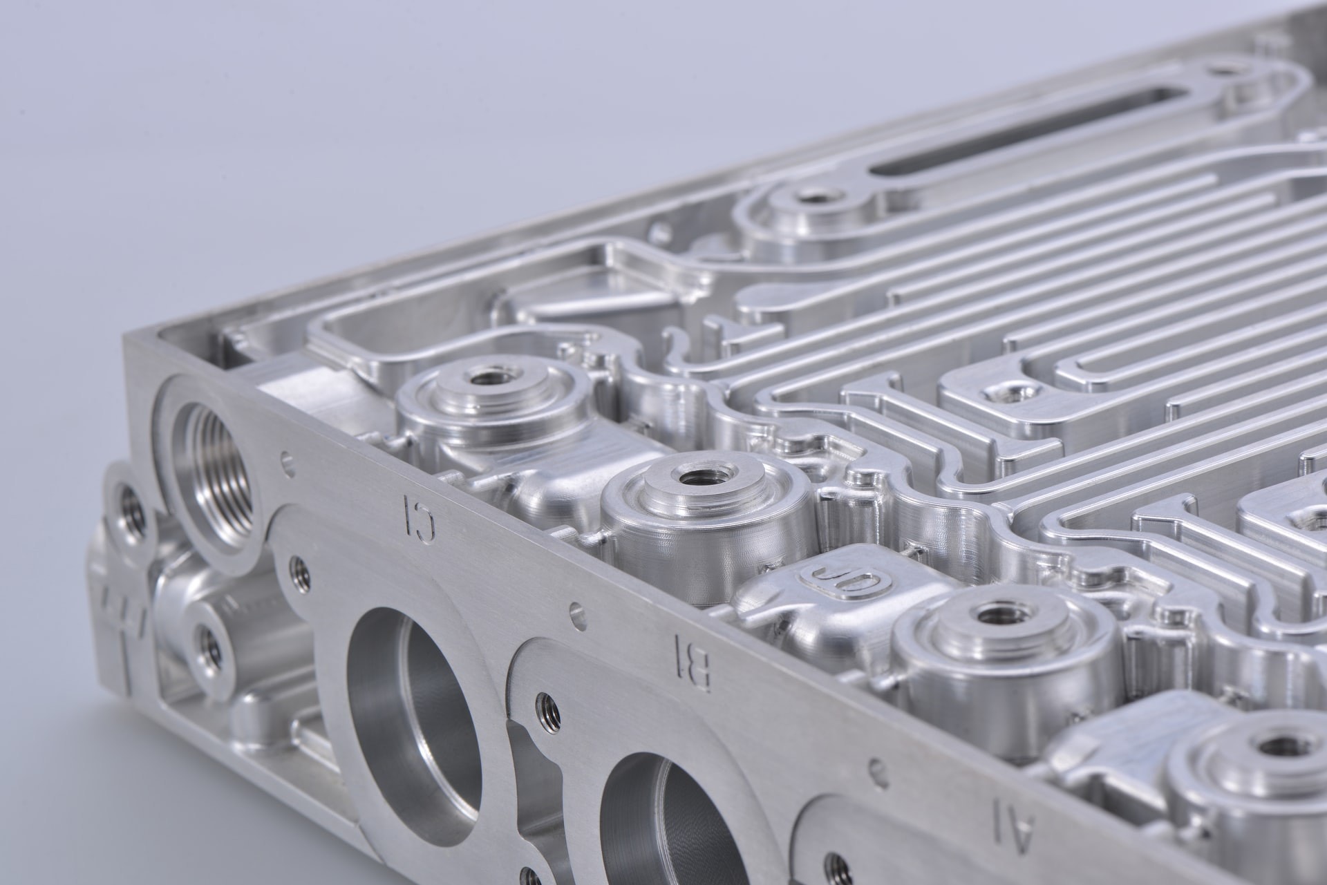
While Pocket cuts constantly (and thus goes faster than Adaptive Clearing), the alternating engagement your tool does with the Adaptive Clearing helps it to cool down. This can be very useful when milling hard and easily heating materials like aluminium.
In short:
- If your material is soft and doesn't pose any heating problem (like plywood, mdf...), you can save time with pockets.
- If your material is hard and/or requires handling heat build-up carefully (like aluminum, plastics...) it might be better to use adaptive clearing.

2D or 3D for Pockets and Adaptive Clearing?
Choosing between 2D or 3D operation is pretty straightforward:
Is the volume you want to mill a straight extruded shape, or is there any variance in the extrusion (chamfers, fillets, bumps, gaps, slots, etc…)?

If what you want to mill is straight (in top view), then pick a 2D operation. Otherwise, use a 3D operation.
Note: If you use a 2D operation instead of 3D on a conic hole for example, you’ll end up with a cylinder.

Drill vs Bore
- The Drill operation will use fixed XY coordinates and plunge in Z. This means that you can only drill out a hole that is the exact same diameter as the end mill you are using, and that dust extraction is not very good.
Therefore this operation is more suited for drill bits than flat end mills which are made to cut.
Drilling with a flat end mill and a milling spindle speed can build up heat very quickly and burn your material!
- The Bore operation with plunge in Z while making a helix in XY. This means that you can “drill out” holes that are up to twice the diameter of your end mill. It is also much faster than using a pocket operation for these holes, and will help chip extraction from the hole you are drilling out, avoiding heat buildup.
Engraving Usage
To engrave text, logos or any other 2D profile in your material, Fusion has an Engrave operation. You can learn more about how to use it in our Branding your project article.
Face Usage
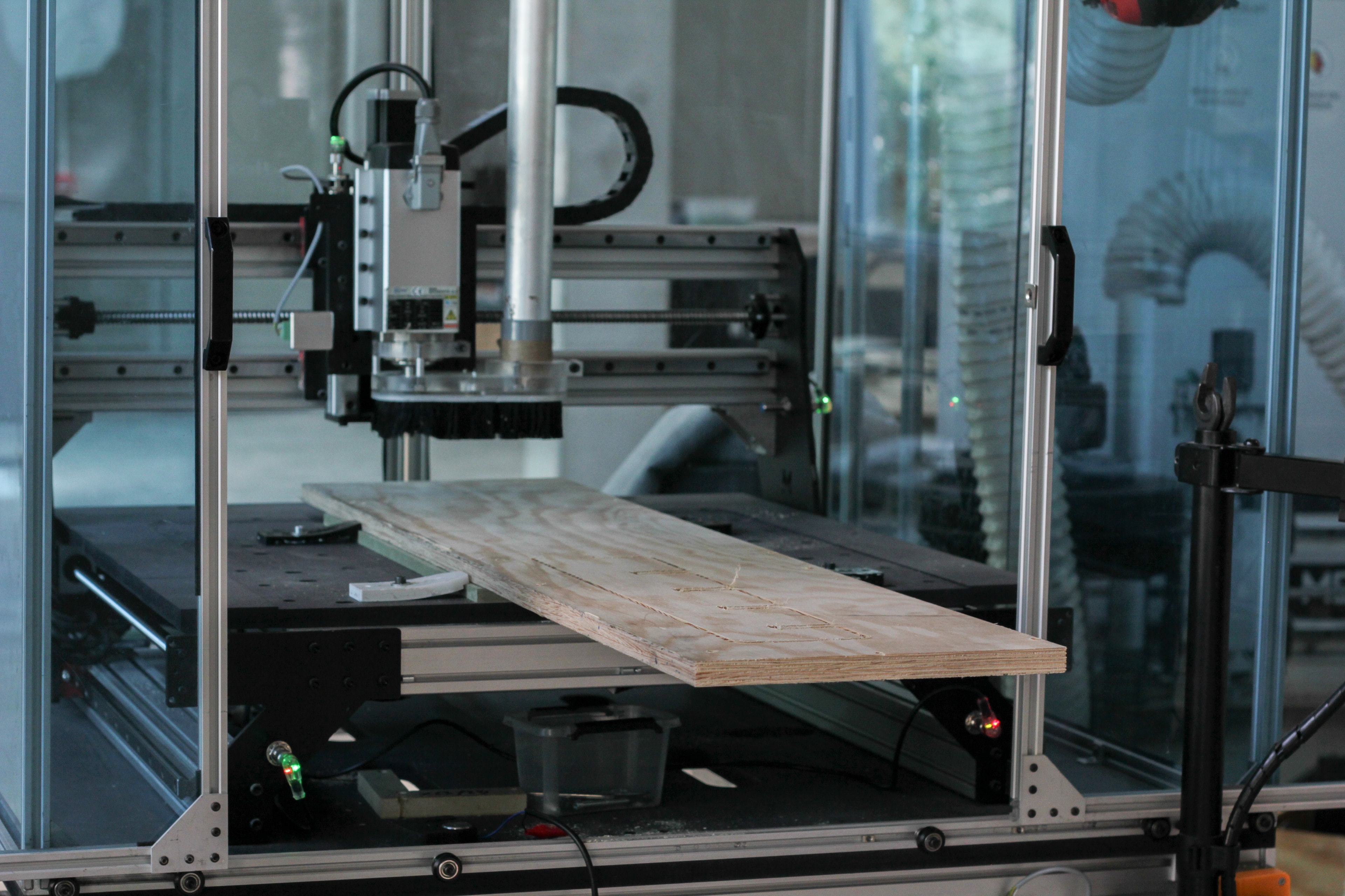
Milling flat surfaces is one of the huge assets a CNC milling machine can offer. Whether you want to use your CNC as a jointer, mill some engineering projects or just flatten your spoilerboard, the Face operation is the one you want to go for to flatten any large surface.

3D Textures
A CNC machine is not only used for 2D operations like cutting contours or making straight holes, it gives you the opportunity to mill 3D textured projects that would have been impossible to achieve by hand (see our "Topographical Map" project).
These kinds of projects often use a 3D Adaptive Clearing operation first (to rough out the stock), and a Scallop operation with a ball end mill next to refine the texture.
The Scallop operation will make a 3D toolpath around a point and make the end mill travel all around the texture you are willing to mill to get rid of the rice field effect left by a 3D Adaptive Clearing operation.
Note: Though you can use a flat end mill with a Scallop operation, it will leave sharper edges than a ball nose end mill and might leave unwanted cutting marks on your piece that will be very hard to sand away.
Part 2: How to Configure Those CNC Milling Operations
Please keep in mind that these are guidelines.
There are an infinite number of possibilities on how to configure milling operations and you will eventually have to tweak these parameters to fit your needs.
2D Contour Configuration
In the first tab Tool: As for any operations, you have to start by selecting the end mill you are planning to use for this operation. In our example, we are going to choose an 8mm flat end mill (from our End Mill Bundle) for which we will use the hard wood preset.

In the second tab Geometry: select the contour you want to mill.
Select the contour you want the tool to reach: this means that if you want to cut a part free, you must select the bottom contour of this shape, not the top one.
If this is an exterior contour, we have to use tabs so that, once the mill reaches the bottom of our piece, the whole body doesn’t come loose (which might be dangerous or damage the part if it touches the tool while it's retracting).

Change the tabs width, height and spacing until you feel the piece will be sufficiently supported but it won’t be a nightmare to clean after the milling is done. Usually, 4 tabs per part are enough.
The third tab, Heights, is used to define various reference heights (for example the safe height above the model where the end mill can travel when it is not cutting).
Editing this tab is optional as Fusion has great preset parameters, but you might have to change these values when using long end mills or when milling really thick stock.

In any case, if you are using clamps to secure your stock to the spoilerboard, we advise you not to change these values. If you’ve secured your stock using screws, you can change the value up to the ones shown in the figure below (not less).

In the fourth tab Passes, you should only edit the Multiple Passes - Maximum Roughing Stepdown value and the Stock to Leave values.
- Maximum Roughing Stepdown : We recommend staying under the radius of the end mill you are using (in this case, under 4 mm) if you are a beginner. As this project would be in hardwood, we will stay safe and take 2.5 mm as step value.

- The Stock to Leave is the offset you want to leave between the model size and the face the tool is actually going to cut (radial for lateral offset, axial for vertical offset). Both can be set to positive or negative values.
This is of course optional and you can uncheck it to mill at the exact dimensions of the 3D model.

The last tab Linking is to tell Fusion how you want your end mill to enter and exit the stock.
We recommend using Ramps instead of Plunges with Leads & Transitions proposed by Fusion.
Your menu tab should thus look like this (remove the Lead In /Lead Out and add a Ramp).
The Ramping Angle depends on the hardness of the material you are milling.
Here are some values we recommend:
- MDF: 20° to 30°
- Plywood: 15° to 20°
- Softwood: 10° to 15°
- Hardwood: 5 to 10°
- Aluminium: 1 to 4°

If you’ve changed the height values in step 3, you will have to edit the “Safe Distance” value. Otherwise, you can use Fusion's default value.
Pocket and Adaptive Clearing Configuration
To mill pockets, you have to choose between 2 different operations (as explained before) : Pocket and Adaptive Clearing. Please refer to the description above to learn more about these two operations.
Just as for the contour operation, we start by defining the Tool : an end mill and its preset we want to use.
We can then select the pocket(s) we want to mill out in the Geometry tab.
Always select the bottom of the pockets (it can be its bottom face or bottom contour)
Like the Contour operation, we can optionally adjust the heights in the third menu tab. Also here, the Passes tab is only used to set Maximum Roughing Stepdown for the passes and the Stock-to-Leave parameters.
The fifth menu tab of this operation is also quite similar to the one we have for the Contour operation, except that we have multiple options for the Ramps.

We recommend using Helix or Profile for all materials, with the angle set to the same values recommended for the contour operation above.
The only difference in parameters compared with the Pocket operation is in the fourth menu tab Geometry.
The Optimum Load should always be inferior to your mill’s radius (in our case, smaller than 4 mm). A higher value would cause the mill to heat up more quickly. Putting a lower value gives it more time to cool down, but also increases the milling time.
The main advantage of Adaptive Clearing over Pocket is that you can generally increase the depth of cut. Where we used 3.5 mm for our cut depth when setting up the Pocket operation, we will now go up to 5 mm depth.

Bore Configuration
There are not many parameters to edit when using the Bore operation. Simply select the right tool, preset and the holes you want to bore out.
As always, you can (optionally) edit the heights to accommodate thick stock or long end mills. There is no need to define ways of going in and out of the stock as the Bore operation will describe a helix when plunging into the material.
You can still configure the angle of that helix though. You can divide by 2 the angle parameters recommended for contour ramps to find angles for boring.

Scallop Configuration
Start by selecting the Tool and the correct Feed and Speed (or a preset)
While the Scallop operations work with any end mill, we recommend using ball nose end mills to achieve the best results.
In the Geometry tab, you have the following fields to edit:
- Machining Boundary: Bounding box (if you want the scallop to be applied on the whole model, otherwise you can select the contour of the area you want to mill)
- Additional Offset (optional) : Play a little with this parameter to make sure the end mill runs a bit outside the model, this makes sure that all of your model will be milled.
- Model: Select the model you want to use the Scallop operation on (if you have many models in the setup)

As always, the third menu tab (Heights) is optional.
In the fourth menu tab (Passes), you will find the most important parameter for this operation: the Stepover.
The Stepover value is what defines the lateral distance between two toolpath lines. The smaller, the more precise your 3D texture will be. But the longer it is going to take to execute the operation…
- Usually, a Stepover of 0.3 to 0.5 mm gives good results while remaining fast enough.
- If it is just to rough out the profile of your model, a Stepover of 0.7 to 1 mm will be faster and leave an ‘OK’ result.
- For very precise work on material that easily scratches (plastics for example) a Stepover of 0.1 mm might be necessary.
It all comes down to how smooth you want the finish to be and the time you are ok for it to take.
You can save a lot of time by removing material roughly before doing a scallop. Use a 3D pocket clearing operation first for example, with a Stock-to-Leave at 0.5mm, this way you can run the scallop faster as it will remove only a small amount of material.
Engraving Configuration
Please refer to our article "Branding Your Project" to learn all about the Engrave operation.
Facing Configuration
To set up a Face operation, start by selecting the tool and set its Feed and Speed (or select a preset).
In the Geometry menu tab, select the contour of the face you want to mill flat.

In the Passes menu tab, edit the following parameters:
- Stock Offset: tool's radius size (to make sure there is no rounded corner visible on the part)
- Stepover: As for the scallop, this is the horizontal distance between two passes of the tool. We recommend setting it to the radius of your tool.
- Multiple Depth: if you have a lot of material to remove to reach the face you want, you might need to do it in multiple steps.
- Stock-to-Leave: (optional)